BuildSTL - August 2016
Intro to Raspberry Pi
by Matt Thomas
Raspberry Pi - History
The Raspberry Pi Foundation was founded in May 2009 in the UK. The Foundation is supported by the University of Cambridge Computer Laboratory and Broadcom. Its aim is to "promote the study of computer science and related topics, especially at school level, and to put the fun back into learning computing."
The Raspberry Pi is a series of credit card-sized single-board computers developed to promote the teaching of basic computer science in schools and developing countries.
In February 2016, the Raspberry Pi Foundation announced that they had sold eight million devices, making it the best-selling UK personal computer.
The Hardware
Raspberry Pi Model A
First Released in February 2012
Only model to come with component video
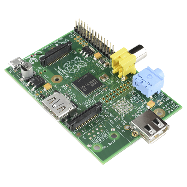
| Gen | Processor | RAM | USB | GPIOs | Network |
|---|---|---|---|---|---|
| 1 | 32-bit Single Core 700MHz | 256 Mb | 1 | 8 |
None Rev 1.2 - RJ45 |
Raspberry Pi Model B
First Released April 2012
The Raspberry Pi Model B sold over 2 Million units within 2 years of mass production.
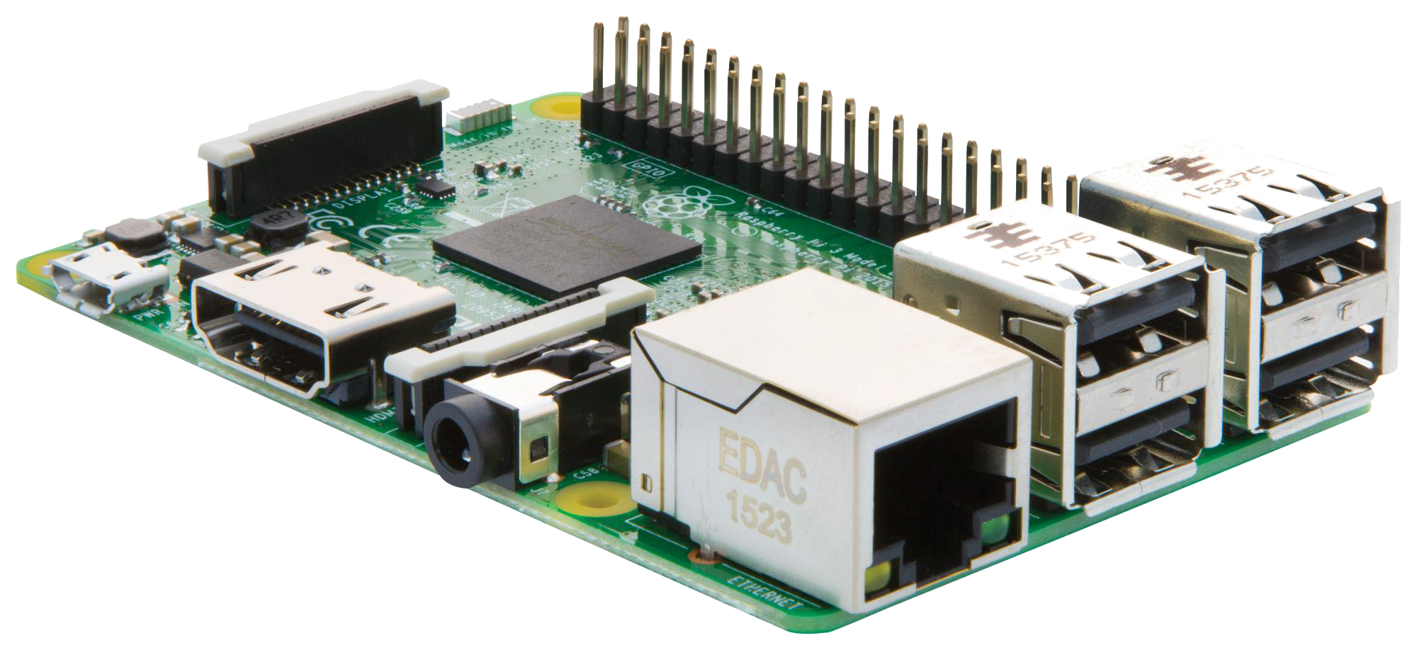
| Gen | Processor | RAM | USB | GPIOs | Network |
|---|---|---|---|---|---|
| 1 | 32-bit Single Core 700MHz | 512 Mb | 2 | 8 (+4) | RJ45 |
| 1 + | 32-bit Single Core 700MHz | 512 Mb | 4 | 17 | RJ45 |
| 2 | 32-bit Quad Core 900MHz | 1 Gb | 4 | 17 | RJ45 |
| 3 | 64-bit Quad Core 1.2GHz | 1 Gb | 4 | 17 | RJ45, WiFi & Bluetooth |
Raspberry Pi Zero
First Released November 2015
Half to one third the size of a Model B.
The only computer to ever be attached and sold inside a magazine.
All connections are in the respective micro formats.
Version 1.3 added camera support
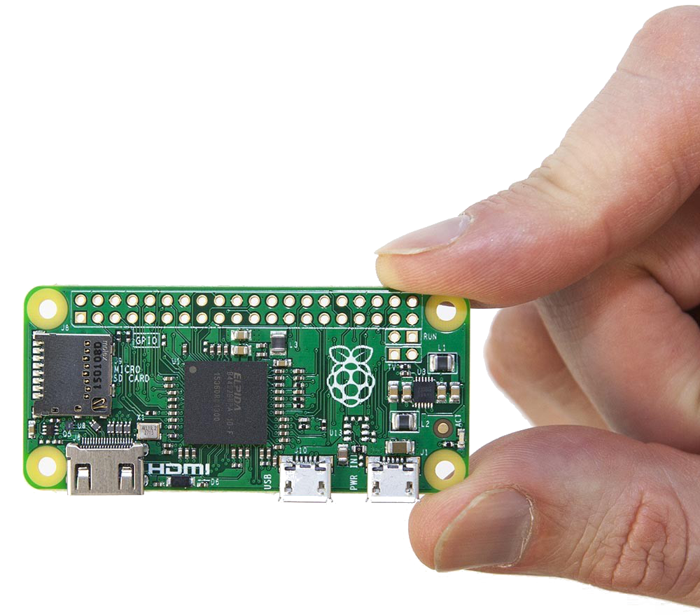
| Gen | Processor | RAM | USB | GPIOs | Network |
|---|---|---|---|---|---|
| 1 | 64-bit Quad Core 1.2GHz | 512 Mb | 1 | 40 | None |
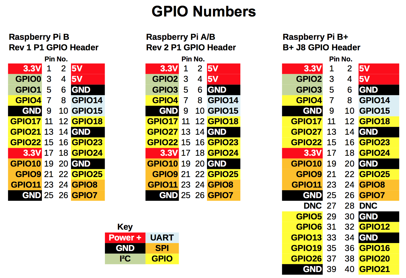
GPIO (General Purpose Input/Output)
When programming the GPIO pins there are two different ways to refer to them: GPIO numbering and physical numbering.
GPIO numbering is GPIO pins as the computer sees them. The numbers don't make any sense to humans, they jump about all over the place, so there is no easy way to remember them. You will need a printed reference or a reference board that fits over the pins.
Physical numbering refers to the pins is by simply counting across and down from pin 1 at the top left (nearest to the SD card).
Generally we recommend using the GPIO numbering (MCD), not board pin numbering.
...GPIO
GPIO pins can be configured to be input or output
GPIO pins can be enabled/disabled
GPIO pins are either analog or digital
Input values are readable
Output values are writable/readable
The Software
Operating Systems
The install manager is called NOOBS which includes numerous OSs.
- Raspbian - Official Debian distribution
- Windows 10 IoT Core - Free (Raspberry Pi 2 or Greater)
Media center operating systems:
- OSMC - free and open source media player based on Linux (XBMC or Kode)
- OpenELEC - Linux based Just Enough Operating System (JeOS) built from scratch as a platform to turn your computer into a Kodi media center.
Others:
- RetroPie - Turn your Raspberry Pi into a retro-gaming machine.
Atari, Commodore, Dreamcast, Game Boy, MAME, Nintendo, Playstation 1, Sega and MORE
OS Installation
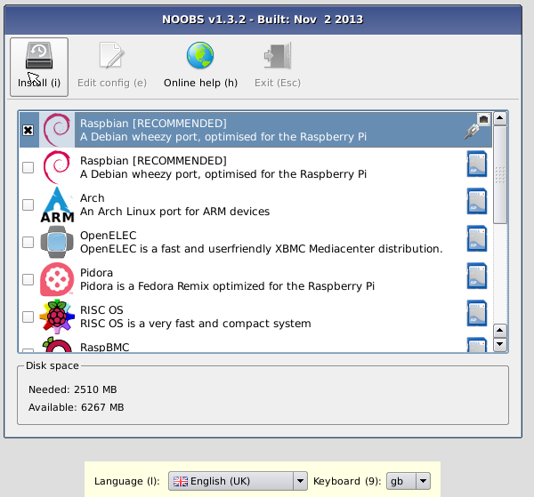
NOOBS
- Download from raspberrypi.org/downloads/noobs
- Extract the archive
- Copy to the Micro SD card
- Boot your Raspberry Pi
Set the language and keyboard appropriately.
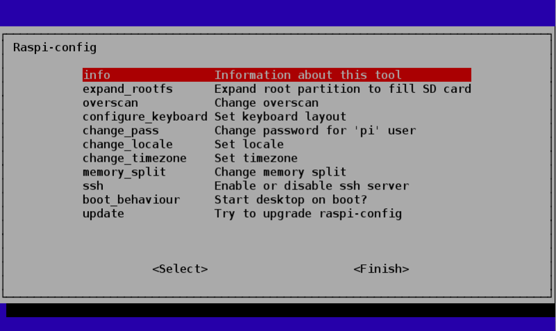
Configuration
raspi-config
Configure keyboard, language, services including ssh and peripherals including audio and camera support.
Notable Preinstalled Software
- Python 2 & 3
- Minecraft
- Mathematica
- Scratch
Recommended Software
- Google Chrome
- IceWeasel (Firefox)
- Terminator
The Demo
If you haven't noticed the entire presentation has been given using a Raspberry Pi.
Now we will demonstrate a Python GPIO application.
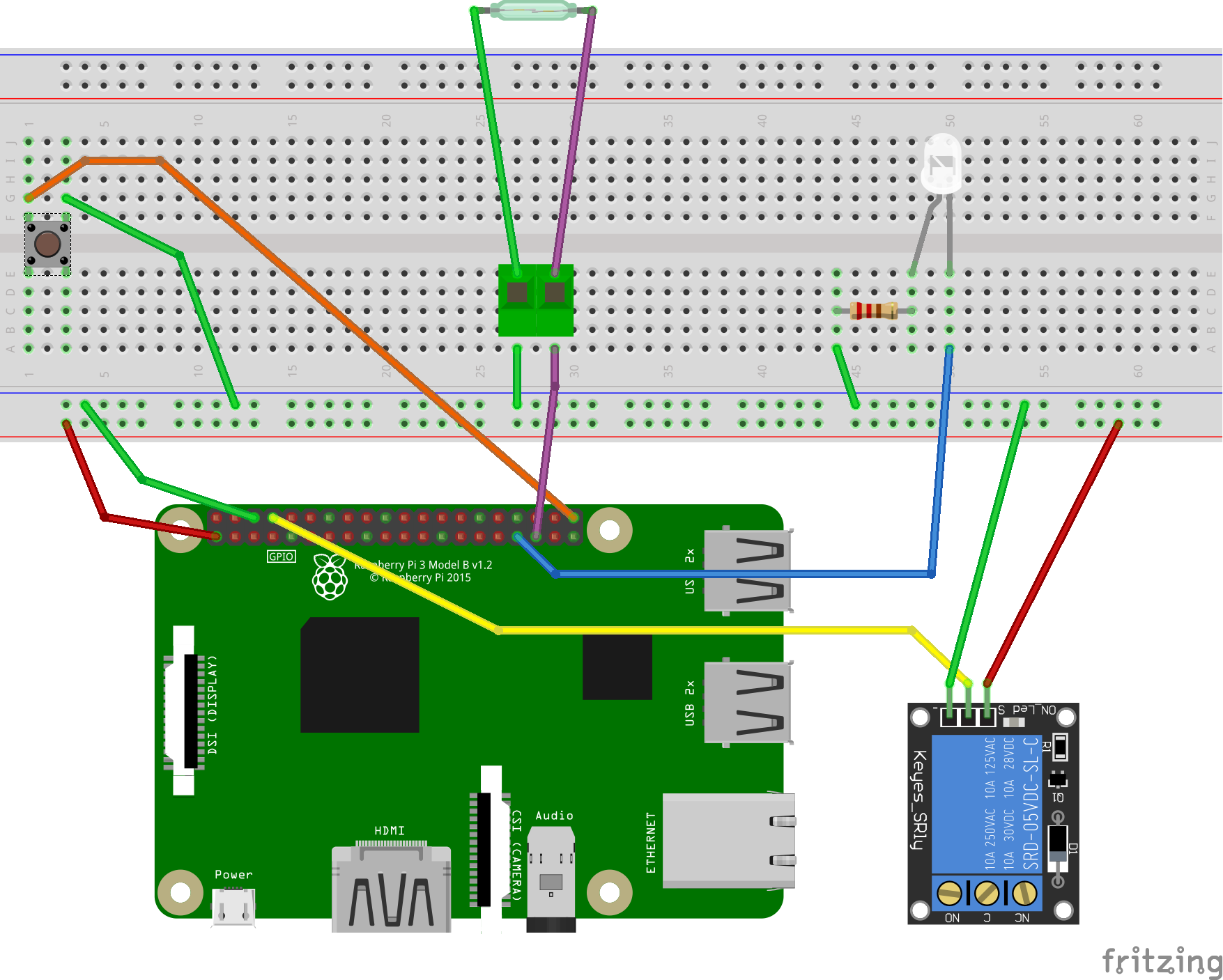
With a Raspberry Pi we will create a garage door controller/monitor
using a relay, reed switch, button & LED.
The Hardware Part
Parts List:
- Raspberry Pi
- Breadboard
- Jumper Wires
- White LED
- 220 Ohm resistor
- 1 Relay Module
- Reed Switch
- Tactile button
The Software Part
Written in Python 3.
Developed and tested entirely on this Raspberry Pi 3 using the IDLE editor.
    # Import the GPIO and time modules
    import RPi.GPIO as gpio
    import time

    # Define GPIO Pins Locations
    relayPin = 4
    switchPin = 21
    ledPin = 13
    reedPin = 19

    # Set up some house keeping variables
    pauseTime = 5
    switchOn = 0

    # Set the pin mode
        # BCM mode references the pin numbers on the chip
        # vs the layout of the board
    gpio.setmode(gpio.BCM)

    # GPIO setup
    gpio.setup(relayPin, gpio.OUT)
    gpio.setup(ledPin, gpio.OUT)
    gpio.setup(switchPin, gpio.IN, gpio.PUD_UP)
    gpio.setup(reedPin, gpio.IN, gpio.PUD_UP)

    # Set the relay pin to be high by default
    gpio.output(relayPin, gpio.HIGH)
    try:
        while 1:
            # Turn on the relay if the button is pressed
            if switchOn == 0 and not gpio.input(switchPin):
                print("Operating the door")
                switchOn = time.time()
                gpio.output(relayPin, gpio.LOW)

            # Turn off the relay after the pauseTime
            if switchOn != 0 and (time.time() - switchOn) > pauseTime:
                switchOn = 0
                gpio.output(relayPin, gpio.HIGH)

            # Turn on the LED if the reed switch is open
            if gpio.input(reedPin):
                gpio.output(ledPin, gpio.HIGH)
            # Turn off the LED if the reed switch is closed
            else:
                gpio.output(ledPin, gpio.LOW)

            # Sleep for the quarter second
            time.sleep(.25)
    except KeyboardInterrupt:
        # Shutdown cleanly if Ctrl-C is pressed
        print("Cleaning things up")
        gpio.cleanup()
Some setup and housekeeping
# Import the GPIO and time modules
import RPi.GPIO as gpio
import time

# Define GPIO Pins Locations
relayPin = 4
switchPin = 21
ledPin = 13
reedPin = 19

# Set up some house keeping variables
pauseTime = 5
switchOn = 0
GPIO Setup
# Set the pin mode
    # BCM mode references the pin numbers on the chip
    # vs the layout of the board
gpio.setmode(gpio.BCM)

# GPIO setup
gpio.setup(relayPin, gpio.OUT)
gpio.setup(ledPin, gpio.OUT)
gpio.setup(switchPin, gpio.IN, gpio.PUD_UP)
gpio.setup(reedPin, gpio.IN, gpio.PUD_UP)

# Set the relay pin to be high by default
gpio.output(relayPin, gpio.HIGH)
The Try/Catch and While Loop
try:
    while 1:

        ...

except KeyboardInterrupt:
    # Shutdown cleanly if Ctrl-C is pressed
    print("Cleaning things up")
    gpio.cleanup()
Controlling Relay via the Push Button
# Turn on the relay if the button is pressed
if switchOn == 0 and not gpio.input(switchPin):
    print("Operating the door")
    switchOn = time.time()
    gpio.output(relayPin, gpio.LOW)

# Turn off the relay after the pauseTime
if switchOn != 0 and (time.time() - switchOn) > pauseTime:
    switchOn = 0
    gpio.output(relayPin, gpio.HIGH)
Controlling the LED via the Reed Switch
# Turn on the LED if the reed switch is open
if gpio.input(reedPin):
    gpio.output(ledPin, gpio.HIGH)
# Turn off the LED if the reed switch is closed
else:
    gpio.output(ledPin, gpio.LOW)

# Sleep for the quarter second
time.sleep(.25)
Putting it all together : 45 lines including comments
# Import the GPIO and time modules
import RPi.GPIO as gpio
import time

# Define GPIO Pins Locations
relayPin = 4
switchPin = 21
ledPin = 13
reedPin = 19

# Set up some house keeping variables
pauseTime = 5
switchOn = 0

# Set the pin mode
    # BCM mode references the pin numbers on the chip
    # vs the layout of the board
gpio.setmode(gpio.BCM)

# GPIO setup
gpio.setup(relayPin, gpio.OUT)
gpio.setup(ledPin, gpio.OUT)
gpio.setup(switchPin, gpio.IN, gpio.PUD_UP)
gpio.setup(reedPin, gpio.IN, gpio.PUD_UP)

# Set the relay pin to be high by default
gpio.output(relayPin, gpio.HIGH)
try:
    while 1:
        # Turn on the relay if the button is pressed
        if switchOn == 0 and not gpio.input(switchPin):
            print("Operating the door")
            switchOn = time.time()
            gpio.output(relayPin, gpio.LOW)

        # Turn off the relay after the pauseTime
        if switchOn != 0 and (time.time() - switchOn) > pauseTime:
            switchOn = 0
            gpio.output(relayPin, gpio.HIGH)

        # Turn on the LED if the reed switch is open
        if gpio.input(reedPin):
            gpio.output(ledPin, gpio.HIGH)
        # Turn off the LED if the reed switch is closed
        else:
            gpio.output(ledPin, gpio.LOW)

        # Sleep for the quarter second
        time.sleep(.25)
except KeyboardInterrupt:
    # Shutdown cleanly if Ctrl-C is pressed
    print("Cleaning things up")
    gpio.cleanup()
GPIO Zero
"A friendly Python API for physical computing".
It makes writing applications that interact with the GPIO interface easier.
More information:
Other Ideas
RetroPi and LCD touch screen mobile gaming RPi
Wedding wall with motion sensor activation of Christmas light
Halloween prop with motion sensor activation, speaking mouth and balloon inflation
pi-top is a DIY laptop you build yourself.
... too many to count!
Additional Resources
- www.raspberrypi.org
- learn.adafruit.com
- learn.sparkfun.com
- www.hackster.io/raspberry-pi
- www.makezine.com/projects
- www.raspberrypi.org/magpi - magazine
-
This Meetup Group!!!
- 95+ members on Meetup with varying degrees of experience.
- Join the STL-Tech#buildstl channel (https://stltech.herokuapp.com/)
Questions?
Feedback...
Meetup: https://www.meetup.com/Build-STL/
Slack: https://stl-tech.slack.com/messages/buildstl/
- Join: https://stltech.herokuapp.com/
Matt Thomas
- Twitter: @matsinet
- Website (Work in progress): http://matsinet.bitbucket.org
Slides: http://matsinet.bitbucket.org/presentations/intro-to-raspberry-pi